FarSync BERT Tester – PCIe
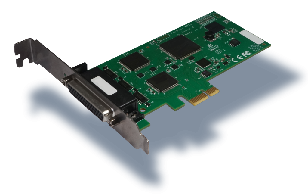
A Bit Error Rate 2 port sync line quality tester for a Windows PC/Server with a PCIe slot. The FarSync BERT provides a comprehensive, simple to use, all in one, line testing utility for testing synchronous lines from your PC up to 20 Mbits/s. There are no extra expensive modules to buy to test different line types.
Product Summary
The FarSync BERT provides a comprehensive, simple to use, all in one, line testing utility for testing synchronous lines from your PC. There are no extra expensive modules to buy to test different line types. All the popular standard BERT test patterns can be selected; the test period can be controlled; real time error counters and full line test statistics are provided as well as support for user controlled error injection.
Lines with network interfaces RS232 (V.24), V.35, RS530 (EIA530), RS422, X.21 (V.11), RS449 and RS485 (4 wire) can be tested with line speeds ranging up to over 2 Mbits/s with the standard speed version or up to 20 Mbits/s with the high speed version.
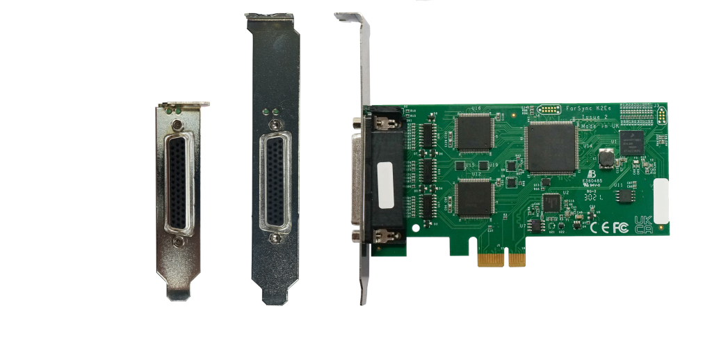
The FarSync K2Ee adapter is fitted in one your PC’s PCIe slots; select one of the cables provided to connect to the line to be tested; the BERT application can then be started and the line quality results are displayed in real time. Multiple FarSync BERT products can be run from a PC.
There is API access for LabVIEW or Windows applications, this allows programmatic control of when tests are run, the tests to be run, and the results obtained.

- BER testing of 1 or 2 lines from your PC using a dual port low profile PCIe adapter
- Tests lines using a set of BERT (Bit Error Rate Test) ITU recommended test patterns
- Supports tests using NRZ, FM0, FM1, Manchester Encoding & Conditioned Di-phase line signalling
- APIs for LabVIEW and native Windows test management applications
- Operates in loopback or point-to-point modes including interoperation with other BER Testers
- Connects to RS232, RS530, RS422, RS485 and with additional cables connects to V.35, X.21, and RS449 network interfaces.
- Line speeds to over up to 2 Mbits/s or 20 Mbits/s depending on the version.
- User controlled error injection facility and custom test patterns
- Round trip delay testing – test the latency of your network
Operation, Installing, Main Features
Special Features
- Single or multiple bit errors can be injected at the user’s request.
- Line data can be inverted to support lines where the balanced pair data lines may have been swapped over or the data supplied has been inverted.
- Inverted receive data can be automatically detected and converted as required.
- Using the supplied loopback connector, the FarSync BERT Tester may be self tested prior to use.
- Audible Alerts on errors and loss of sync.
- Handling of custom clock rates.
- Line clock speed display.
Using the FarSync Line Monitor
We offer two variants of the FarSync BERT PCIe:
- FarSync BERT Tester – PCIe – Synchronous – maximum test speed 2 Mbits/s on each port
- FarSync BERT HS Tester – PCIe – Synchronous – maximum test speed 20 Mbits/s on a single port and 16Mbits/s on 2 ports.
Configuration vs Test speed
Noting the overall maximum test speed for the product, the following lower limits apply to achievable test speeds. Most of these are physical limitations for the factor in question rather than a limitation of the product. Where several factors apply to a test mode, the data rate limit is the lowest rate for the individual relevant factors.
| Factor | Max Achievable Data Rate |
|---|---|
| V.24 interface mode | 384 Kbits/s |
| Multi-drop testing | 753 Kbits/s |
| Coded clock modes (FM0, FM1, NRZI, Manchester Encoding, Conditioned Di-Phase) | FarSync BERT Tester – PCIe ; 2 Mbits/s FarSync BERT HS Tester – PCIe ; 10 Mbits/s |
| User defined data patterns | Dependent on length of data pattern (see examples below) |
| V35 or Interal clocking +Terminal Timing (TT) | 17 Mbits/s |
| External clocking + Terminal Timing (TT) | 18 Mbits/s |
The maximum supported line rate for user defined data patterns depends on the length of data pattern provided. For example:
| Pattern type | Pattern length | Maximum achievable data rate |
|---|---|---|
| Hex | 6 bytes | FarSync BERT Tester – PCIe ; 2 Mbits/s FarSync BERT HS Tester – PCIe ; 14 Mbits/s |
| 100 bytes | 832 Kbits/s | |
| 300 bytes | 448 Kbits/s | |
| Binary | 252 bytes | 1088 Kbits/s |
| 504 bytes | 512 Kbits/s | |
| 2048 bytes | 128 Kbits/s |
The latest FarSync BERT software provides support for the following FarSync adapters:
FS4204 FarSync BERT Tester – PCIe
FS4206 FarSync BERT HS Tester – PCIe
on 64-bit versions of:
Windows 11, Windows 10, Windows 8.1*, Windows 7*,
Windows Server 2019, Windows Server 2016 and Windows Server 2012 (excluding IoT editions)
*Note that with Windows 8.1 and Windows 7, these versions of Windows are
no longer supported by Microsoft. It is therefore not possible to provide assurances for correct operation on those
platforms.
Frequently asked questions regarding the FarSync BERT are available here.
Technical Functionality
Test Patterns
A wide variety of pseudo random and fixed test patterns may be configured on the FarSync BERT used to test the line. ITU compliant test pattern recommendations are supported, these are compatible with other industry standard BER Testers.
Synchronous Lines
The following pseudo random patterns are ITU-T compliant, they are used to test synchronous lines:
- 63: 26−1 – including a max of 5 sequential zeros and 6 sequential ones
- 511: 29−1 – including a max of 8 sequential zeros and 9 sequential ones
- 2047: 211−1 – including a max of 10 sequential zeros and 11 sequential ones
- 215−1 – including a max of 14 sequential zeros and 15 sequential ones
- 220−1 – including a max of 19 sequential zeros and 20 sequential ones
- 223−1 – including a max of 22 sequential zeros and 23 sequential ones
- QRSS: 220−1 – modified to transmit a maximum of 14 consecutive zeros
The following fixed patterns can be used to test synchronous lines:
- 1:7 (1/8, 1-in-8) – 1 mark followed by 7 spaces
- 1/16 (1:15, 1-in-16) – 1 mark followed by 15 spaces
- 2/8 (2:6, 2-in-8) – 2 marks in 8 bits (0100 0010…)
- 3/24, 3-in-24 – 3 marks in 24 bits (0010 0010 0010 0000 0000 0000…)
- MK – all 1s
- SP – all 0s
- 1:1 – alternating 1s and 0s
- FOX (see ITU recommendation R.52 for definition)
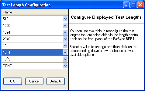
In addition to the standard test patterns the user can supply their own custom test pattern of up to 64Mb, test patterns do not have to be byte aligned.
Test Modes
- The FarSync BERT Tester can act as either the physical DTE or DCE
- The tests can be run in loopback or point-to-point modes including interoperation with other suppliers BER Testers
- Line tests can be invoked manually via the GUI, via batch command files or via the API
- Tests can be run for a set number of bits or for a defined period of time

The FarSync BER Tester has a full graphical user interface that enables the user to select and configure the test to be run. The final test results are displayed via the user interface. The status of each test is reported in real-time via the GUI whilst each test is being run. Drop down windows provide additional detailed test results.
The FarSync BERT Tester products is supplied with the following cables, these are the most common network connector types used on synchronous lines.
- RS232 (V.24) DTE – using cable FCR2
- RS530 (RS422) DTE – using cable FCR2
- RS485 (4 wire) – using cable FCR2
Additional cables supporting the following other interfaces may be purchased separately if required.
- V.35 DTE – using cable 2 TCV1 (requires the FCR2 cable supplied with the product)
- X.21 (V.11) DTE – using 2 TCX1 (requires the FCR2 cable supplied with the product)
- RS499 (V.36) DTE – using 2 TC449 (requires the FCR2 cable supplied with the product)
- X.21 (V.11) DCE – using cable Null-MX
- RS232 (V.24) DCE – using cable Null-MR4 (requires the FCR2 cable supplied with the product and a TCX1)
- RS530 (RS422) DCE – using cable Null-MR4 (requires the FCR2 cable supplied with the product)
- NRZ
- FM0
- FM1
- Manchester Encoding
- Conditioned Di-phase
The line test results displays industry-standard count values (e.g. ITU-T G.821) which help indicate the quality of the line under test. The result table shows error rates, expressed as a percentage or in scientific / engineering format.
- Bits – number of bits received
- Blocks – number of blocks received
- Block Errors – number of blocks received with errors
- Framing Errors – number of incorrectly framed asynchronous characters received
- Parity Errors – number of asynchronous characters received with incorrect parity
- Errored Secs (ES) / Unavailable Secs (US) – number of secs during which one or more errors has been detected
- Severely Errored Secs (SES) – number of secs during which the bit error rate has exceeded the threshold
- Severely Errored Secs (SES) – number of secs during which the bit error rate has exceeded the device’s SES threshold
- Available Secs (AS) / Error Free Secs (EFS) – number of secs during which no errors have been detected
- Loss of Sync (LOS) – number of times synchronisation has been lost
The network latency can be measured using the round trip delay feature which is particularly useful for testing wireless networks. The results are shown as a readout and graphically with the spread of times measured.

- Single or multiple bit errors can be injected at the user’s request.
- Line data can be inverted to support lines where the balanced pair data lines may have been swapped over or the data supplied has been inverted.
- Inverted receive data can be automatically detected and converted as required.
- Using the supplied loopback connector, the FarSync BERT Tester may be self tested prior to use.
- Audible Alerts on errors and loss of sync.
- Handling of custom clock rates.
- Line clock speed display.
Calibration of the FarSync BERT Products
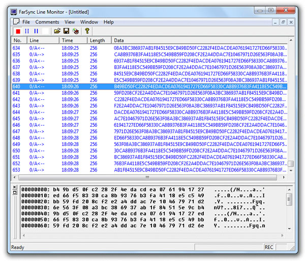
The product is supplied with multi-channel line monitor software that allows the user to record, display and store line traffic transmitted and received by the BER testing, so for example the test patterns sent and received can be viewed.
LabVIEW API
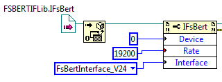
The LabVIEW API allows the BERT functions to be invoked, and results to be read, by LabVIEW programs (VIs). Sample Vis are provided to illustrate the use of the API. All the features available from the GUI are supported by the LabVIEW API. Both 64 bit and 32 bit LabVIEW access is supported.
Windows API
The BERT’s COM API allows its functions to be invoked, and results supplied back, programmatically from Windows applications. All the features available from the GUI are supported by the COM API. Sample applications are supplied in Python, C# and VBS.
The FarSync BERT can also be used in command line/script mode with the configuration being specified by command line parameters – the results are written to a log file.
Order information
| Product Name | Description | Product Code |
| FarSync BERT Tester - PCIe | BER (Bit Error Rate) line quality tester for testing synchronous lines from a PCIe card, tests X.21, RS232, V.35, RS422, RS485 (4 wire), RS530, RS449 network interfaces. Product includes:
Synchronous - maximum test speed 2 Mbits/s on each port Note: Requires a PC, not supplied. | FS4204 |
| FarSync BERT HS Tester - PCIe | BER (Bit Error Rate) High Speed line quality tester for testing synchronous lines from a PCIe card, tests X.21, RS232, V.35, RS422, RS485 (4 wire), RS530, RS449 network interfaces. Product includes:
Synchronous - maximum test speed 20 Mbits/s on a single port and 16Mbits/s on 2 ports. Note: Requires a PC, not supplied. | FS4206 |
| BERT Calibration Certificate | FarSite Issued calibration certificate for FarSync BERT USB and PCIe variants. Testing and verification of FarSync BERT is conducted through specific crystal timing tests against a high accuracy GPS clock. | FS4950 |
| Additional Cables Available | ||
| TCV1 | V.35 DTE single port adapter cable, M34M connector, 0.5 metres, requires the FCR2 cable supplied with the product. | FS6053 |
| TCX1 | X.21 (V.11) DTE transition cable, DB15M connector, 1 port EIA-530 to X.21, 0.5 metres | FS6052 |
| TC449 | RS449 DTE transition cable, DB37M connector, 1 port EIA-530 to RS449, 1.5 metres | FS6054 |
| Null-MX | X.21 double shielded crossover cable, DB15F connector to DB15F connector, 0.5 metres. Converts DTE presentation to DCE. | FS6090 |
| Null-MR4 | Combined RS530 (RS422, EIA530) and RS232 (V.24) double shielded crossover cable, DB25F connector to DB25F connector, 0.5 metres. Converts DTE presentation to DCE | FS6097 |
