Network Interface Connector Standards - Defined and Explained
What is an X.25 Network?
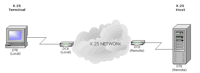
An X.25 network provides a means by which one X.25 DTE (a Terminal or Host of some kind) can exchange data with one or more other X.25 Host, on the other side of the network.
Data is carried within individual packets – X.25 is often referred to as a Packet Switching Protocol. This makes it similar to a TCP/IP network – the difference is that IP networks employ a Connectionless protocol: each packet is routed according to the information within that packet (typically by using the Destination Address).
By contrast, X.25 is a Connection-Oriented protocol: the routing information used by the network is carried only in the packets used to establish the connection; thereafter addressing information is not required. This does, however, mean that the X.25 network switching nodes need be aware of each connection, unlike IP routers.
X.25 Layers
The X.25 protocol is divided into 3 layers (or Levels); TCP/IP, on the other hand is divided into 4 layers.
| Layer | Description | X.25 | TCP/IP equivalence |
|---|---|---|---|
| 1 | Physical Layer | V.24, X.21, V.35, etc | Same as X.25, and others not normally used by X.25 (too many to mention) |
| 2 | Data Link Layer | LAPB | Many, such as PPP, SLIP, Cisco HDLC, etc and even X.25 itself (see below)! |
| 3 | Network Layer | X.25 PLP | IP |
| 4 | Transport Layer | (none) | TCP or UDP |
Each of these layers is independent. The Physical layer includes the mechanical and electrical aspect of communications – in other words, cabling. The X.25 Data Link Layer provides the reliable link between the DTE and the DCE (or Network), and the X.25 Packet Layer Protocol (PLP) provides the information necessary to make and maintain a connection across the network.
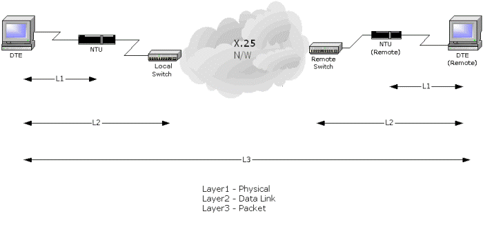
It’s probably most useful to think of Layer 1 as being the physical connection to the network NTU or modem, Layer 2 as being the Logical Link between the DTE and the local network switching node, and a Layer 3 Virtual Circuit as being the connection to the remote DTE.
An X.25 Network User Address (NUA) is much like a telephone number, being a string of digits, and can be up to 15 digits in length. The NUA on a typical network will be 12 digits in length, with another 2 digits for the subaddress.
X.25 Data Transfer takes place within the context of connections, known as Virtual Circuits. There are 2 types of Virtual Circuit:
- Switched Virtual Circuit (SVC)
- Permanent Virtual Circuit (PVC)
An X.25 SVC is very similar to a Telephone Call – one party initiates the connection (the “calling” party – or “client”, to use TCP/IP terminology), and the other party receives the connection (the “called” party or “server”). The client supplies the address of the server, much like someone making a telephone call has to dial the phone number of the called party. An X.25 SVC is therefore much like a TCP/IP connection.
A PVC is somewhat akin to a telephone hotline that goes to a single pre-defined destination, except that there is no Call setup – data can be sent immediately, rather than having to wait for an answer. This does, however, mean that there is a problem knowing whether anything is present at the other end of the connection when data is transmitted.
Unlike PSTN, with an X.25 network it is possible to make several virtual circuits simultaneously – this is because X.25 connections can be multiplexed down a single X.25 link. Multiplexing is achieved by splitting the link into Logical Channels.
X.25 is a reliable protocol, and was designed for use with networks with significant error rates on each link. With TCP/IP, error recovery is end-to-end (any retransmissions take between the client and the server). TCP/IP thus does not require a reliable link layer protocol like LAPB , With X.25, each link has error recovery procedures.
An X.25 network therefore performs better than TCP/IP when there are significant error rates on the links. The downside is that X.25 networks cannot forward the packets until they have been completely received, resulting in transit delays. TCP/IP therefore performs better than X.25 when error rates are low – error rates are typically very low on modern networks.
Another key difference between TCP/IP and X.25 is that TCP data transfer is stream-based, whereas X.25 data transfer is packetized. This is a concept that often catches out new users of TCP – fortunately with X.25, when you send a block of bytes, that same number of bytes is delivered to the far end as a single block. By contrast, with TCP, if, for example, transmitting 2 blocks of 2000 bytes, the remote peer might receive it as a single block of 4000 bytes, or more likely, as 3 or more separate blocks.
That’s not to say that the X.25 data doesn’t get split up – many X.25 Data Packets may be required to carry the block of 2000 bytes in the example above. The difference is that the X.25 Data Packets can be chained together by use of something called the “M-bit“, thus allowing the receiver to link them together again.
Many applications using X.25 rely upon X.25’s ability to preserve the boundaries of blocks of data (although it is of course also possible to use X.25 to implement a simple character stream).
In order to achieve the same effect over TCP, an additional encapsulation layer is required, such as Cisco’s RBP (Record Boundary Preservation) protocol. There are very many others ways of encapsulating data blocks over TCP, however, which is why conversion between X.25 and TCP is not straightforward, and the reason for the existence of the FarSync TCP-X25 Gateway, which supports a number of different encapsulations, including Cisco RBP.
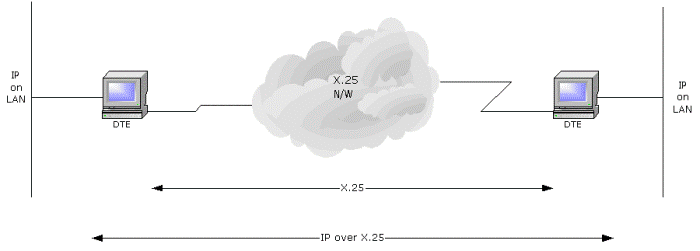
It is possible for an X.25 network to carry TCP/IP data. This is normally accomplished using the rules defined in RFC-1356. This is useful where an existing X.25 network is used to form the backbone of part of a TCP/IP network. In this case, the entire X.25 network would itself be as Layer 2 as far as TCP/IP is concerned.
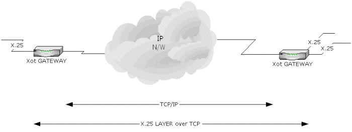
X.25 virtual circuits can be carried over a TCP/IP network – this is done using the XOT protocol, RFC-1613. This is useful where an X.25 network has been replaced, but the X.25 terminals and hosts are required to continue to work unchanged.
For XOT, TCP/IP replaces X.25 layer 2. However, there is a separate TCP connection per X.25 Virtual Circuit, so it’s not exactly the same as running X.25 Layer 3 running on directly on top of TCP.
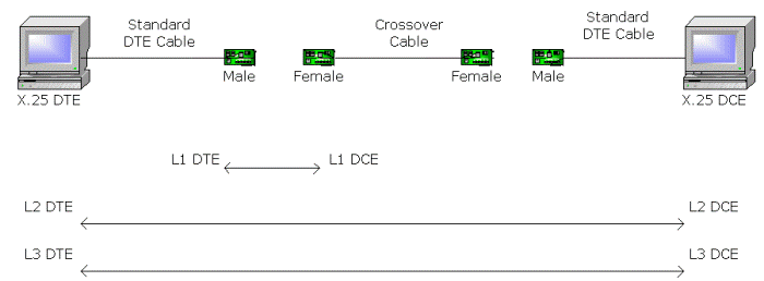
As well being used to connect to a network, X.25 can be used point-to-point. Point-to-Point X.25. This is commonly deployed when connecting to an legacy host computer, and it’s also useful to be able to connect in this way when testing a terminal or host, in the absence of an X.25 network.
When used Point-to-Point, one end of the link must be a DTE, and the other a DCE. To confuse matters, the DTE/DCE configuration is potentially independent at each of the 3 X.25 layers; it’s a good idea (if you have the choice) to configure all 3 layers to be the same type.
The X.25 Guide was proudly written by FarSite Communications Ltd.