Interface Standards
V.35 is a specification for a connector type, pin allocation and signal level used for synchronous communications interfaces in many parts of the world. The original standard was for a now obsolete modem. The signal electrical characteristics used in V.35 interfaces are a combination of V.11 (for clocks and data) and V.28 (control signals).
Interface Characteristics
V.35 uses differential interfaces for the clock and data signals which are the only signals requiring high switching speeds for high-speed communications. Throughput of up to 10Mbps is typical, dependent on the equipment and cable used. The other signals are unbalanced (single wire) and normally incur a minimum of state changes. Separate clock lines are used for receiving and transmitting data.
Interface Applications
V.35 interfaces are common in some parts of the world primarily due to its adoption by telephone companies and their equipment suppliers. Commonly used bit-rates are 64Kbps, 128Kbps, 256Kbps etc. The X.21/V.11 interfaces used for the data and clock signals enable high throughput but maximum distances are not as high as for X.21/V.11 due to the use of single-ended V.28 interfaces for the control signals. Typical protocols used over V.35 interfaces are HDLC, X.25, SNA and PPP.
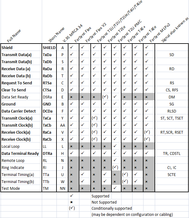
Interface Connector Types and Pinouts
The MRAC-34 type (ISO 2593) connectors is used for synchronous connections. The signals used by the overwhelming majority of applications are marked in bold.
The V.35 standard is supported on the FarSync range of communications products