World renowned communication products you can rely on
Our products are trusted by a prestigious list of international organisations and in a wide range of technology sectors.

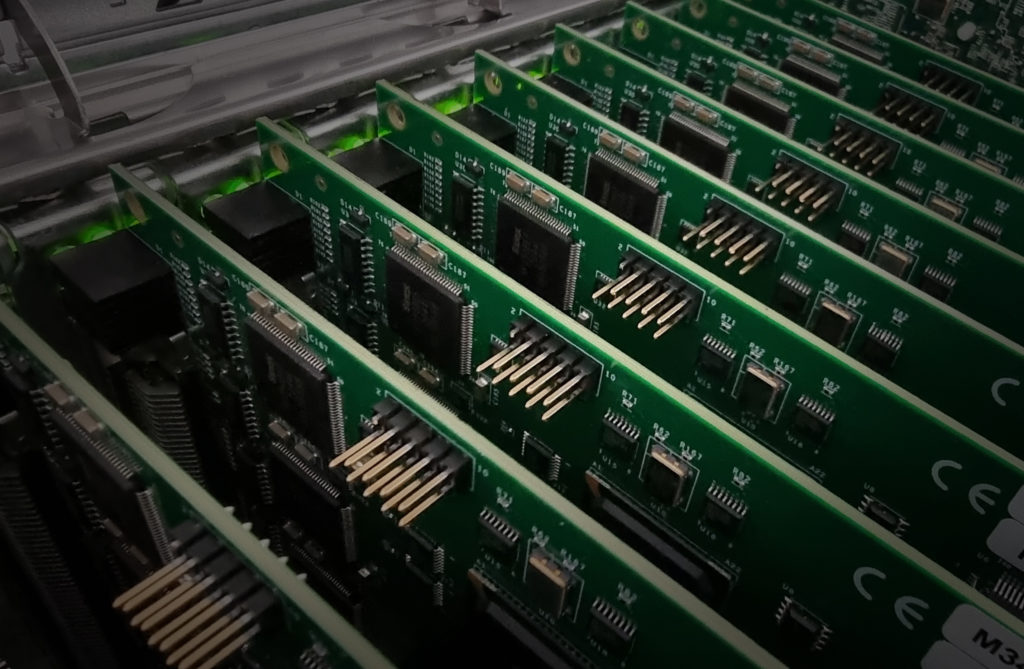
Delivering high end comms products since 1998
FarSite supply the world’s biggest range of USB, PCI Express, Universal PCI, PMC bus communications adapters. Since 2015 we have developed and sold a range of IoT solutions for smart city applications.
-

Inhouse development
Hardware and software all developed and manufactured in the UK
-

Exceptional support
Our customer support team provides an excellent level of assistance to end customers around the world
-

Services and solutions:
Long standing experienced FarSite resellers around the world

Services and solutions:
Development services
FarSite Communications provide technical consultancy and development services to clients in various sectors. Click here to contact us with details of your particular requirement.
- Consultancy
- Hardware and Software custom development
- Product Customisation
- Technical expertise list
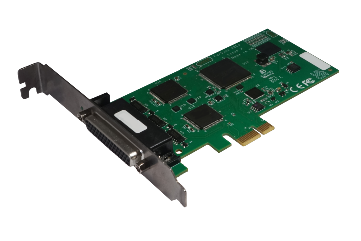
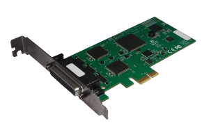
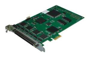
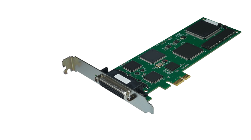
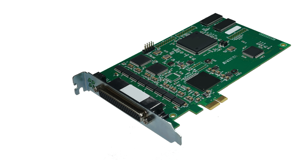
WAN Adapters
FarSite supply the world’s biggest range of USB, PCI Express, Universal PCI & PMC bus communications adapters with E1, X.21, V.35, RS232, EIA530, RS422 & RS449 WAN interfaces for synchronous and asynchronous operation
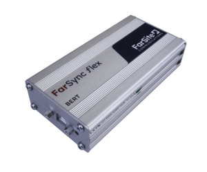
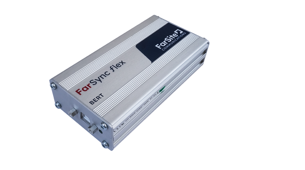
BER Testers
The FarSync BERT Tester provides a comprehensive, simple to use, line testing utility for asynchronous and synchronous lines. Standard BER test patterns are used with real time error counters, user controlled error injection, full line test statistics and APIs.
X.25 Adapters and XOT
FarSite supply the world’s biggest range of X.25 adapters and XOT software for PCs, Servers and Laptops. There’s a USB adapter; 1, 2 & 4 port Universal PCI adapters; 2 & 4 port PCI Express adapters and a PMC adapter.
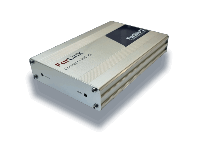
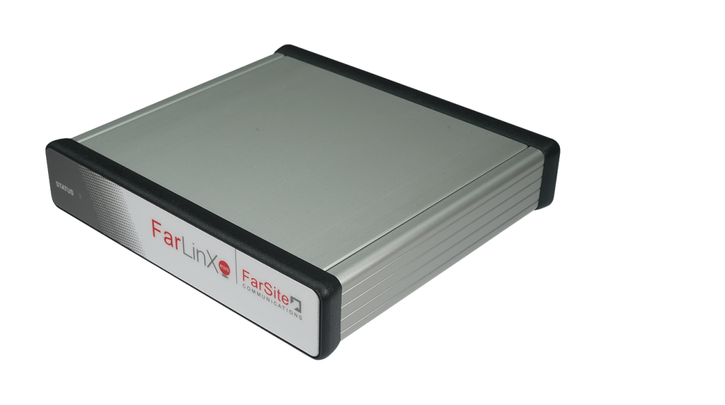
Gateways
TCP/IP to X.25 Gateway products for fast dependable inter-connection of TCP/IP, XOT & X.25 networks. FarSite’s specialised gateways handle connection management and transfer of a very wide variety of types of data traffic between TCP/IP, XOT & X.25 networks.
More than 2,000 customers in over 110 countries
FarSite’s products are trusted and used in a diverse range of applications across the globe. See below some of the key industries that trust FarSite’s products to do the job!
- Defence Communications
- Space Exploration
- Telecommunications
- Payment Authorisation
- Air Traffic Control