The only calibration that your FarSync BERT Tester requires is to verify the correct operating frequency of the internal crystal oscillator used for clock generation.
This can be performed without disassembling the unit by measuring the generated clock at the DCE interface.
We recommend testing your FarSync BERT’s calibration annually.
Calibration steps
You will need:
- Your BERT tester
- For the USB BERT, a KCR1 cable; for the PCIe BERT, you will need a FCR2 cable
- A DB25 breakout box
- A calibrated frequency meter
To calibrate your FarSync BERT Tester:
- Install the BERT drivers and software on the host system to which you will attach your BERT
- Plug in the USB BERT or install the PCIe BERT device
- Allow ten minutes with your system running for the BERT to stabilise at the current ambient temperature
- Use the BERT software to configure the BERT port. You will need to set the following settings:
- RATE: 1024000,
- MODE (M): SYNC,
- INTERFACE (I): RS530,
- CLOCK (C): INT
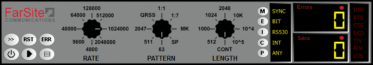
Settings for calibration - Attach your cables: the KCR1 cable will connect to the USB BERT and the FCR2 cable will connect to the PCIe BERT
- Attach the breakout box. This needs to be on the Port A side of the FCR2 cable when using the PCIe BERT
- Start (►) the pattern generator using the BERT software
- Use your frequency meter to measure the frequency of the clock on pin 17, using the ground reference on pin 7 on the breakout box
The expected measured frequency at these settings is 1.024MHz with a variation tolerance of ±100ppm. If the measured frequency falls outside these limits, the device should be returned to FarSite for recalibration, using the standard FarSite returns procedure. Please contact FarSite support with any queries.